
Blower motor fan doesnt work in any position


Thread Starter
|
Junior Member
Joined: Oct 2022
Posts: 2
I have a 2002 SC2 and I followed richpin's guide. I tested the ground on the fan and it has good continuity. But when I test the purple power wire I see 12 volts. I have replaced the blower motor, blower switch and the resistor. My original symptoms were during long usage of the fan it would eventually shut off. So I would turn it off and let it cool down and it would work. But now it doesn't work at all in any position. Don't know if its related but my dash lights stopped working when headlights turn on and abs light has always been on since I owned the car.
So I dug through the factory service manual
1. With ignition on I see 12 volts on either side of the HVAC (15 amp) fuse and IGN3 (30 amp) fuse. And I see 12 volts at terminal "D" (Brown wire) of blower switch
2. With blower motor switch on low, I see 12 volts at terminal "D" (Yellow wire) at blower motor resistor and I see 12 volts at terminal "C" (Dark Blue wire) at blower resistor.
3. I have continuity between terminal "C" (Dark Blue wire) at blower motor resistor and terminal E1 of blower motor relay.
4. Disconnect blower motor relay. Have 12 volts at terminal D1 (Red wire) at blower motor relay.
5. Used a jumper wire from terminal D1 (Red wire) to terminal F2 (Purple wire) and the fan turns on and spins.
With Blower Relay Component test I hooked 12 volts from the battery up to terminal F1 and hooked terminal A1 to battery negative side. But when I check continuity between terminals D1 and F2 I see no continuity. I used paper clips on the back side for F1 and A1 and used paperclips on the front side of the relay panel for D1 and F2
If I try to check for continuity at the relay ground I am not seeing it (0.00) Is that A1 on the backside of fuse box that leads to the I/P splice pack 1 to the under the drivers dash, left of steering column?

Super Moderator
Joined: Jul 2005
Posts: 12,410
From: Slightly off center
Please take either scans converted to PDF or photos of each page of the service manual which describes the test and has the wiring diagrams.
In most vehicles, the max setting bypasses the blower motor resistor and is basically a feed straight off battery voltage with nothing really in between. If you can get the motor to run on the Max setting straight off the battery then the motor is good. However, if you have lost the ground at the motor or at the relay, nothing will be patched through because it won't be a complete circuit.
Sounds like an issue with the relay or the wiring attached to it that leads to the blower motor. There's quite a bit of current spinning that motor so I will not be surprised if you took off the fuse panel and found burnt contacts underneath which might explain your lack of continuity. But again I really need to see the schematics to figure this out
Last edited by derf; Oct 6, 2022 at 12:11 AM.
Thread Starter
|
Junior Member
Joined: Oct 2022
Posts: 2
Finally took apart the fuse box, pics of fuse box: https://imgur.com/a/23TnIOT
Hard to tell in the second pic but its not quite as round as the other ones looks like it needs to be bent back. How do you remove a single wire so I can fully inspect the wire? Is the fuse box side (male metal tabs) fine if theres signs of melting?
Troubleshooting: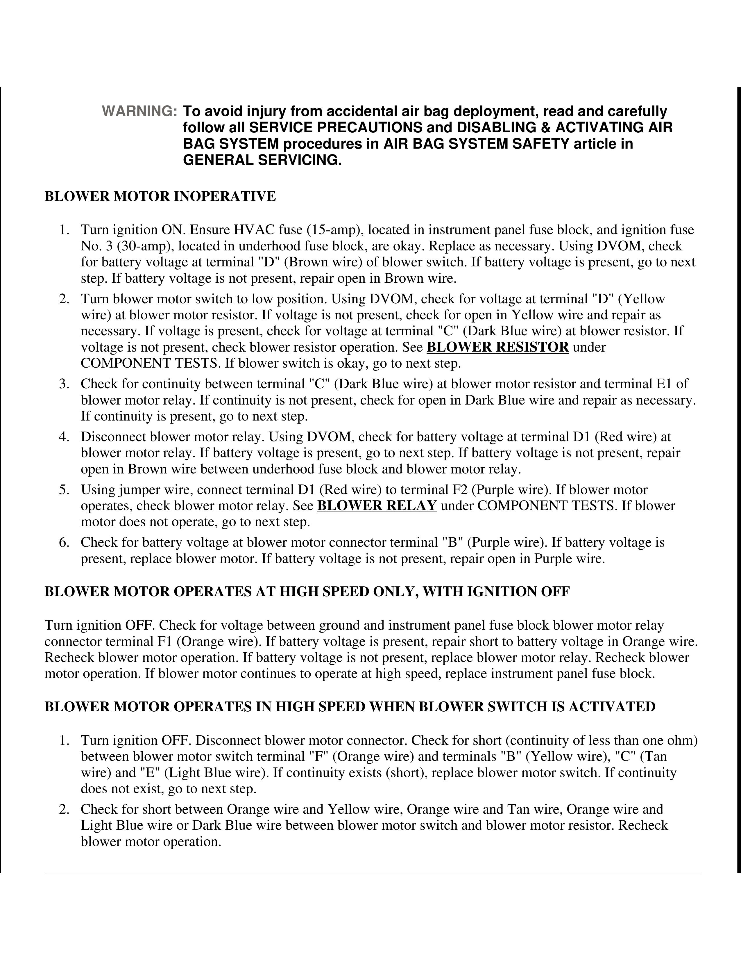
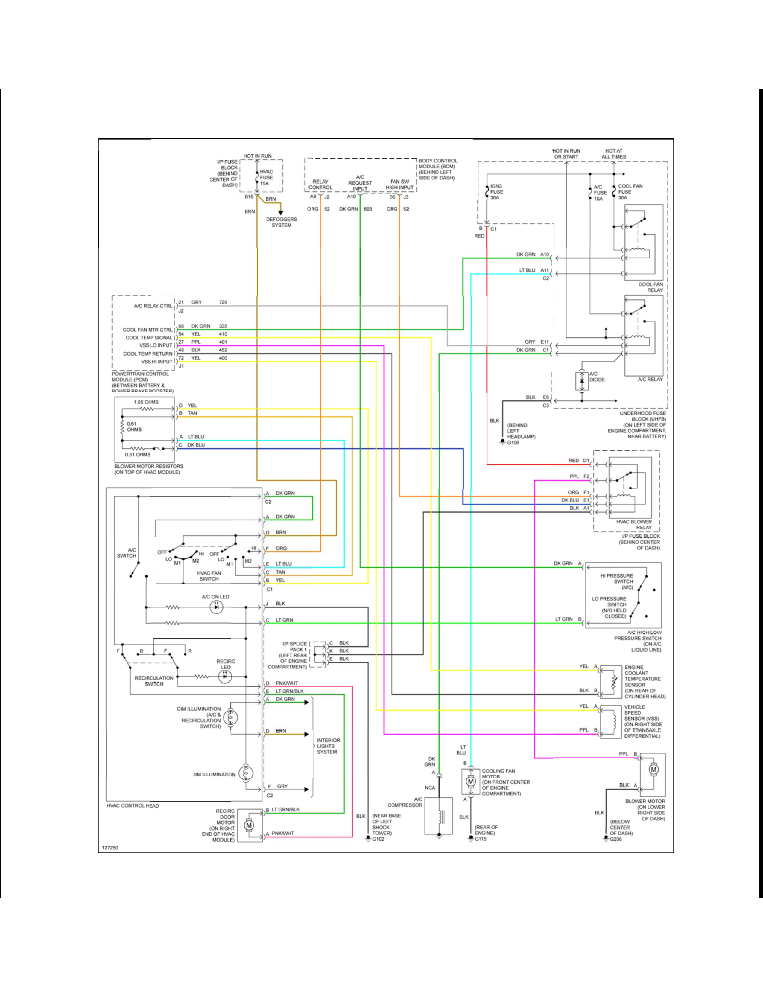
Wiring diagram:
Hard to tell in the second pic but its not quite as round as the other ones looks like it needs to be bent back. How do you remove a single wire so I can fully inspect the wire? Is the fuse box side (male metal tabs) fine if theres signs of melting?
Troubleshooting:
Wiring diagram:


Thread
Thread Starter
Forum
Replies
Last Post