
Rev limiter- '93 SC2 DOHC, manual trans


Super Moderator
Joined: Jul 2005
Posts: 12,387
From: Slightly off center
oops was writing the above while you were posting.....
To me, the only thing that is going to trigger the 4K rev limiter is if the car is moving <3mph and you mash the pedal.
I'd trace the wiring back to the PCM and see what you've got.
Did you bring over the PCM in the swap?
Did the speedometer work before removing?
To me, the only thing that is going to trigger the 4K rev limiter is if the car is moving <3mph and you mash the pedal.
I'd trace the wiring back to the PCM and see what you've got.
Did you bring over the PCM in the swap?
Did the speedometer work before removing?
Last edited by derf; Jul 21, 2015 at 11:25 AM.

Super Moderator
Joined: Jul 2005
Posts: 12,387
From: Slightly off center
just re-checked 91-02 Chilton schematics vs 91-93 chilton manual.
The 91-93 manual uses the yellow (hi) and purple (lo) as the example diagram in the VSS section and the schematics section (fig 236 PCM schematics 1993).
The 91-02 manual shows the same yellow/purple color coding. (pg 12-22 Sec A16, models through 95)
No wire color changes are indicated anywhere in the circuit.
However, the turbine speed sensor has a Dark Blue w white stripe and grey w/red stripe on it. Light green could be gray, and yellow stripe being red --well not all that convincing.
What IS semi convincing is that both wires for the turbine speed sensor are striped, while both wires for the VSS are solid. Therefore, if you look at the wire colors at the PCM, you'll be able to positively ID whether you've pulled the TSS or the VSS.
PCM Locations
VSS:
Yellow: J2A09
Purple: J2A10
Speed OUT signal from PCM having processed VSS signal: J2A02
__________
TSS:
Turbine Speed Sensor "B": Dark Blue w white stripe: J2E15
Turbine Speed Sensor "A": Grey w red stripe: J2E16
_______________
Remember, I am not working from FSMs. I have found the information above from two Chilton Manuals and they are 100% in agreement with each other.
That doesn't make them right.
But the blue w white stripe makes me wonder if you've accidentally pulled the TSS, not the VSS. I believe they are identical parts but obviously the info is used for different purposes. The VSS is on the side of the tranny nearest the back of the car, up by the bell housing.
Ultimately, I would review/confirm the wiring at the PCM . Doing so will tell you if there is any signal from the VSS getting to the PCM -- which I doubt it is. The VSS output is 16 pulses per revolution and it doesn't kick in until 3 mph. So this will be too fast for the DCV setting, technically, but may "average" out to some non zero crap reading, but a reading nonetheless.
Actually, an analog meter would be better than a digital for this test b/c although the reading itself will be garbage, you may be able to infer the pulses via needle movement. Or use an oscilloscope to see the actual pulses coming through.
Alternatively, you could cheat and just look at the SPEED OUT signal on J2A02--actually no you can't b/c you don't know if the PCM is ok internally.........
As stated above, I think you may have confused the TSS w the VSS.
_____________
This post took a long time to write, so even if it's useless to you, please pretend it was helpful.
EDIT:
Added
Link to
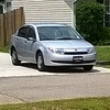
Thumbnail of VSS sensor location (note side of bell housing)
The 91-93 manual uses the yellow (hi) and purple (lo) as the example diagram in the VSS section and the schematics section (fig 236 PCM schematics 1993).
The 91-02 manual shows the same yellow/purple color coding. (pg 12-22 Sec A16, models through 95)
No wire color changes are indicated anywhere in the circuit.
However, the turbine speed sensor has a Dark Blue w white stripe and grey w/red stripe on it. Light green could be gray, and yellow stripe being red --well not all that convincing.
What IS semi convincing is that both wires for the turbine speed sensor are striped, while both wires for the VSS are solid. Therefore, if you look at the wire colors at the PCM, you'll be able to positively ID whether you've pulled the TSS or the VSS.
PCM Locations
VSS:
Yellow: J2A09
Purple: J2A10
Speed OUT signal from PCM having processed VSS signal: J2A02
__________
TSS:
Turbine Speed Sensor "B": Dark Blue w white stripe: J2E15
Turbine Speed Sensor "A": Grey w red stripe: J2E16
_______________
Remember, I am not working from FSMs. I have found the information above from two Chilton Manuals and they are 100% in agreement with each other.
That doesn't make them right.
But the blue w white stripe makes me wonder if you've accidentally pulled the TSS, not the VSS. I believe they are identical parts but obviously the info is used for different purposes. The VSS is on the side of the tranny nearest the back of the car, up by the bell housing.
Ultimately, I would review/confirm the wiring at the PCM . Doing so will tell you if there is any signal from the VSS getting to the PCM -- which I doubt it is. The VSS output is 16 pulses per revolution and it doesn't kick in until 3 mph. So this will be too fast for the DCV setting, technically, but may "average" out to some non zero crap reading, but a reading nonetheless.
Actually, an analog meter would be better than a digital for this test b/c although the reading itself will be garbage, you may be able to infer the pulses via needle movement. Or use an oscilloscope to see the actual pulses coming through.
Alternatively, you could cheat and just look at the SPEED OUT signal on J2A02--actually no you can't b/c you don't know if the PCM is ok internally.........
As stated above, I think you may have confused the TSS w the VSS.
_____________
This post took a long time to write, so even if it's useless to you, please pretend it was helpful.
EDIT:
Added
Link to
Thumbnail of VSS sensor location (note side of bell housing)
Last edited by derf; Jul 22, 2015 at 12:39 PM.
Super Moderator
Joined: Jul 2005
Posts: 12,387
From: Slightly off center
Baby come back, any kind of fool could see, There was something in everything about you...
Baby come back, you can blame it all on me, I was wrong, and I just can't live without you{Player}
They got their (overdue/my fault) 10-day/10 post intro email this a.m. along with a bunch of others with a full addd'l ten days to stay (or should I go now?) {Clash}
I like doing that kinda research and like it even more when it helps put another Satty back into circulation. I guess it makes me smile. I found it hard, it's hard to find . Oh well, whatever, never mind {Nirvana}.
Super Moderator
Joined: Jul 2005
Posts: 12,387
From: Slightly off center
Shame you folks never came back....would love to know what the deal was...
Oh, in the spirit of goodnaturedness I just stumbled across the part num for the ALDL OBD I adapter that permits real time OBDI data to be read bt the appropriate Actron scanner.
Actron CP9127 AutoScanner ALDL Cable Kit
Available on Amazon right now (to my amazement) -- prob the last ones in existence. Has that other style pinout on the other end so must attach to the correct scanner.
Hope your racing is going well.....
If you'd like to rejoin us, drop me an email at the address listed in my signature

Thread
Thread Starter
Forum
Replies
Last Post